- Information Classification
Ceramic Failure: Cracking, Thermal Shock & Mounting Stress
Technical ceramics are selected for demanding applications because of their hardness, wear resistance,
electrical insulation, heat resistance and dimensional stability.
However, even a well-selected ceramic material can fail if the component geometry, mounting method,
thermal environment or mating-part tolerances are not properly controlled.
Understanding ceramic failure therefore requires more than looking at the ceramic material itself.
Engineers should evaluate the complete system: material, geometry, assembly, thermal cycling,
mechanical loading and surrounding components.
This guide explains common causes of ceramic component failure and what engineers and buyers
should review before prototype validation or mass production.
Common Ceramic Failure Symptoms
| Failure Symptom | Possible Cause | What to Check First |
|---|---|---|
| Cracking | Mounting stress, impact, thermal stress or stress concentration | Assembly load, geometry, contact area and temperature changes |
| Edge Chipping | Handling impact, sharp edges or local contact stress | Edge geometry, packaging, assembly tools and contact points |
| Fracture During Assembly | Excessive preload, interference fit or misalignment | Tolerance stack, fixture alignment and clamping force |
| Failure After Thermal Cycling | Temperature gradient or thermal expansion mismatch | Mating materials, wall thickness and heating/cooling conditions |
| Unexpected Wear | Poor mating material selection, surface condition or alignment | Surface finish, clearance, load and mating component |
1. Ceramic Cracking Caused by Mounting Stress
One of the most common causes of ceramic cracking is not the ceramic material itself,
but stress introduced during assembly.
Technical ceramics are hard and dimensionally stable, but they do not deform in the same way as many metals
or engineering plastics. If a ceramic component is clamped too tightly, installed with excessive interference
or forced into a misaligned assembly, local tensile stress can develop.
This type of ceramic mounting stress may cause immediate fracture or create damage that becomes visible
only after repeated operation.
Important assembly factors include:
- Clamping force
- Press-fit or interference-fit conditions
- Flatness of mating surfaces
- Contact area
- Alignment
- Tolerance stack
- Metal housing deformation
For custom ceramic components, assembly conditions should therefore be reviewed together with the ceramic drawing.
2. Ceramic Thermal Shock and Thermal Cycling
Heat resistance and thermal shock resistance are not the same thing.
A ceramic may tolerate a high operating temperature but still experience stress when one area heats or cools
much faster than another.
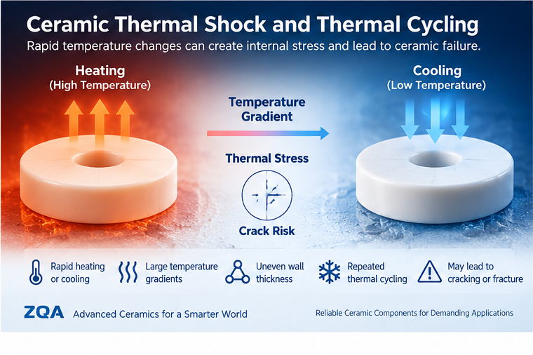
This temperature difference can create internal thermal stress. Repeated heating and cooling may also produce
ceramic thermal cycling failure if the component geometry or surrounding assembly restricts expansion
and contraction.
Factors that can increase thermal stress include:
- Rapid heating or cooling
- Large temperature gradients
- Uneven wall thickness
- Local hot spots
- Rigid metal mounting structures
- Different thermal expansion behavior between mating materials
When reviewing ceramic thermal shock, engineers should consider the entire assembly rather than only
the maximum temperature listed on a ceramic material data sheet.
3. Geometry Can Create Stress Concentrations
Component geometry has a major influence on ceramic reliability.
Sharp internal corners, abrupt changes in wall thickness, deep grooves, small radii or locally thin sections
can concentrate mechanical or thermal stress.
In some applications, a small geometry change can improve stress distribution without changing the overall
function of the component.
Typical areas worth reviewing include:
- Internal corners
- Transitions between thick and thin sections
- Mounting holes
- Slots and grooves
- Edges near clamping locations
- Threaded or mechanically retained areas
This is why drawing review is important before tooling or mass production.
4. Tolerance and Fit Problems Between Ceramic and Metal Parts
Ceramic components are frequently assembled with metal housings, shafts, terminals, bushings or frames.
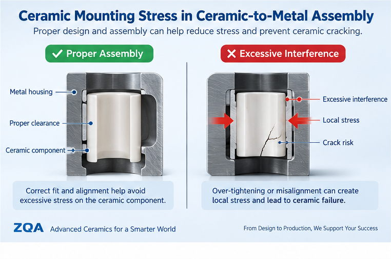
Problems can occur when the dimensional relationship between the ceramic and the mating part creates excessive
local stress.
For example, an interference condition that is acceptable for two metal components may not be suitable
for a brittle ceramic-to-metal interface.
Engineers should review:
- Critical dimensions
- Fit and clearance
- Concentricity
- Flatness
- Position of mounting features
- Thermal expansion of mating materials
- Assembly sequence
The drawing should define the dimensions that are functionally critical rather than applying unnecessarily
tight tolerances to every surface.
5. Surface Damage and Machining Defects
Technical ceramic components may require grinding, polishing or precision machining after sintering.
Surface condition can influence performance, especially around highly loaded areas, edges,
holes or mating surfaces.
Potential concerns include:
- Edge damage
- Surface scratches
- Micro-chipping
- Machining marks in critical areas
- Poor edge transitions
Inspection requirements should therefore reflect how and where the ceramic component will be loaded in service.
6. Impact and Handling Damage
Ceramic components can provide excellent wear resistance and hardness, but they generally require more careful
handling than ductile metal parts.
Impact during transportation, assembly or maintenance can damage edges or introduce cracks.
The component may still appear usable but fail later when exposed to mechanical or thermal loading.
For sensitive precision ceramic parts, packaging, handling procedures and assembly tools should be considered
part of the quality-control process.
Alumina vs Zirconia: Does Material Choice Affect Failure Risk?
Material selection also affects how a ceramic component responds to mechanical and thermal loading.
Alumina is widely used where electrical insulation, hardness, wear resistance and dimensional stability are important.
Zirconia is often considered for applications where greater fracture toughness and resistance to mechanical damage
are required.
However, material selection should not be based on a single property.
Engineers should also consider:
- Electrical requirements
- Wear conditions
- Mechanical loading
- Temperature
- Geometry
- Mating components
- Cost target
A different ceramic material cannot always compensate for poor geometry or excessive assembly stress.
Ceramic Failure in EV Charging Components
Ceramic components used in high-voltage connector systems may combine electrical insulation,
structural positioning and thermal requirements.
In these applications, failure analysis should consider not only the ceramic material but also terminal alignment,
housing geometry, assembly load, thermal cycling and surrounding metal components.
For connector designs where conventional polymer insulation approaches its thermal or electrical performance limits,
alumina ceramic can provide stable electrical insulation and dimensional performance under demanding operating conditions.
Related product:
Alumina Ceramic Housing for EV Charging Connectors
Ceramic Failure in EV Water Pump Components
EV and electronic water pumps can use different ceramic components for different functions.
Examples may include ceramic plates, rings and precision shafts.
Each component experiences different operating conditions, so failure prevention should be evaluated separately.
A plate may be affected by thermal cycling and mounting conditions, while a precision shaft may be more sensitive
to alignment, surface condition, bearing fit and rotational loading.
Related ceramic components:
Ceramic Heat Dissipation Plate
99% Alumina Ceramic Ring for NEV Water Pump
Zirconia Ceramic Shaft for Water Pumps
How to Reduce Ceramic Failure Risk Before Mass Production
Reducing ceramic failure risk should begin before mass production rather than only after a component cracks or chips.
Before prototype evaluation, engineers should review:
- 2D drawing and 3D model
- Ceramic material and grade
- Critical dimensions and tolerances
- Mating component materials
- Assembly method
- Clamping or press-fit conditions
- Operating temperature
- Thermal cycling conditions
- Mechanical loading
- Surface finish requirements
- Prototype validation method
This system-level approach can help identify potential failure risks before tooling and larger production quantities
are committed.
When Should You Request an Engineering Drawing Review?
A drawing review is especially useful when:
- A metal or plastic component is being converted to ceramic
- The ceramic will be assembled into a metal housing
- The design includes thin walls or abrupt geometry transitions
- The component experiences repeated heating and cooling
- Critical tolerances affect assembly or performance
- A previous ceramic component has cracked or chipped
- The application requires prototype validation before mass production
The purpose of the review is not simply to manufacture the drawing exactly as supplied.
It is to determine whether the material, geometry, tolerances and assembly conditions are suitable for the intended application.
Early engineering review can help identify ceramic failure risks related to material selection,
geometry, tolerances and assembly conditions.
Need Help Reviewing a Ceramic Component Design?
Zhengqiang provides drawing-based ODM development for custom alumina and zirconia ceramic components used in
EV charging, water pumps, electrical systems and appliance applications.
Our engineering team can review your drawing, material requirements, critical dimensions,
assembly conditions and estimated quantity before prototype evaluation.